832.781.8343
![]()
 Figure 3
 Figure 4
Trylon
Socket and Trylon adaptor integration method (Fig. 1)
Step 1. When using a shoe board vertical alignment jig (Fig. 5 and 13), place the dynamically aligned prosthesis and shoe in the vertical alignment jig and outline the shoe on the shoe board. Step 2. After the positive plaster model has hardened, remove dynamic alignment components and reinforce the distal end of the definitive socket with additional layers of glass or carbon fibers, saturate the distal reinforcement with epoxy, and apply moderate negative pressure using vacuum bag molding. Step 3. Place the predetermined OAL (including the shoe, Trylon/foot, and optional socket and Trylon adaptors) in the transfer fixture. Integral Trylon alignment is determined by moving the shoe on the shoe board until the vertical longitudinal axis of the Trylon intersects the middle of the knee side to side and front to back (Fig 6 and 7). Foot rotation is maintained by keeping the medial or lateral border of the shoe outline parallel. Step 4. Temporarily adhere the socket adaptor to the distal socket reinforcement (Fig 8). Step 5. Reinforce the socket adaptor base with glass or carbon fiber cloth for lamination of the socket and socket adaptor with an appropriately sized adaptor lamination dummy and conventional resin transfer molding (Fig. 9 and10). Do not sand the shoulder that contacts the base of the Trylon adaptor (Fig. 11). Step 5. Replace the socket and Trylon assembly in the transfer jig and tighten all adaptor set screws to 16 ft/lbs. (Fig. 12 and 13).
Socket receptacle method (Fig. 2)
Steps 1 - 3 are the same as the adaptor method. Step 4. Temporarily adhere an appropriately sized receptacle lamination dummy to the distal reinforcement using the centering pin. Step 5. The amount of fiber reinforcement determines the wall thickness of the receptacle, ranging from 1/8 to 3/16 inch. Laminate the socket and receptacle dummy using conventional resin transfer molding (RTM) technology (Fig. 9 and 10). Step 6. Remove the dummy by inverting the distal cap and screwing down the 5/16 buttonhead screw. Step 7. Invert the relative position of the shoe board and socket in the vertical transfer jig. Clean and sand the socket receptacle and the proximal Trylon spiral members. Step 8. Pour epoxy into the receptacle and around the sanded spiral members and reinforce with chopped glass or carbon fibers and receptical after centering pin.
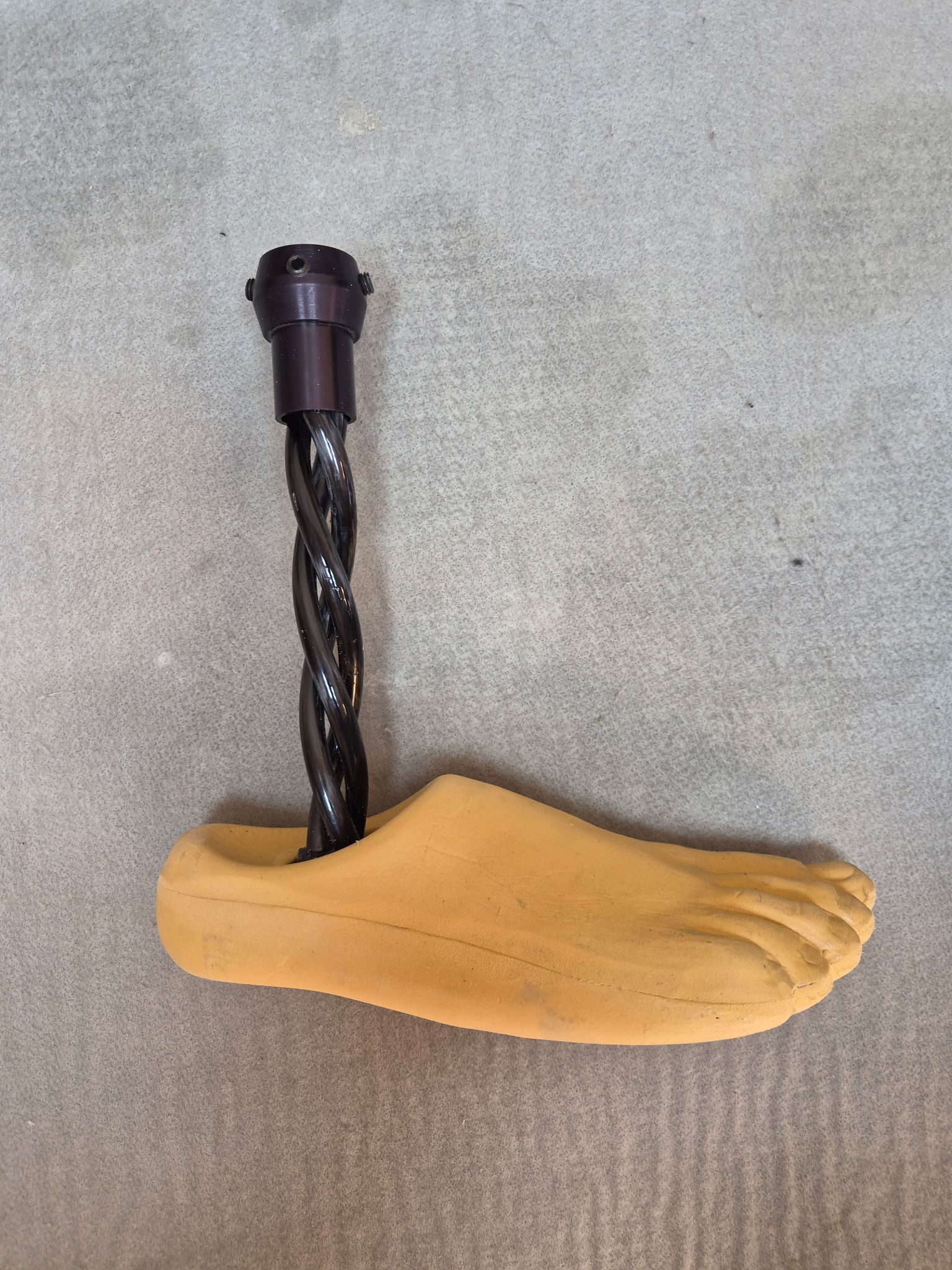 Figure 1 Figure 1 |
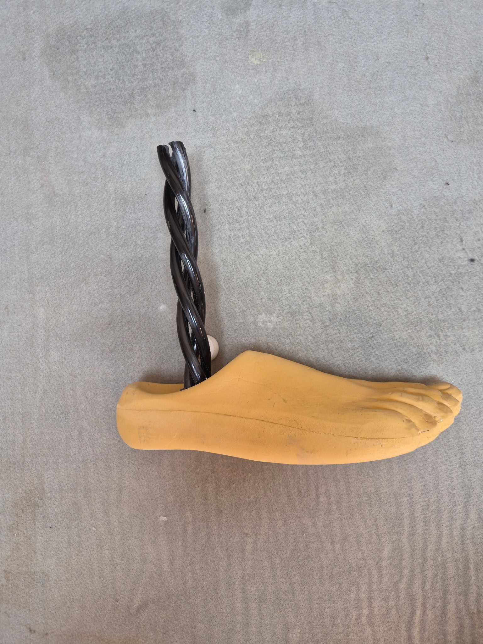 Figure 2 Figure 2 |
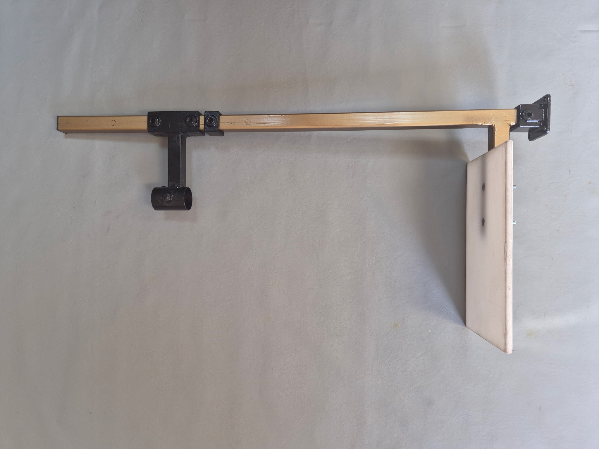 Figure 5 Figure 5 |
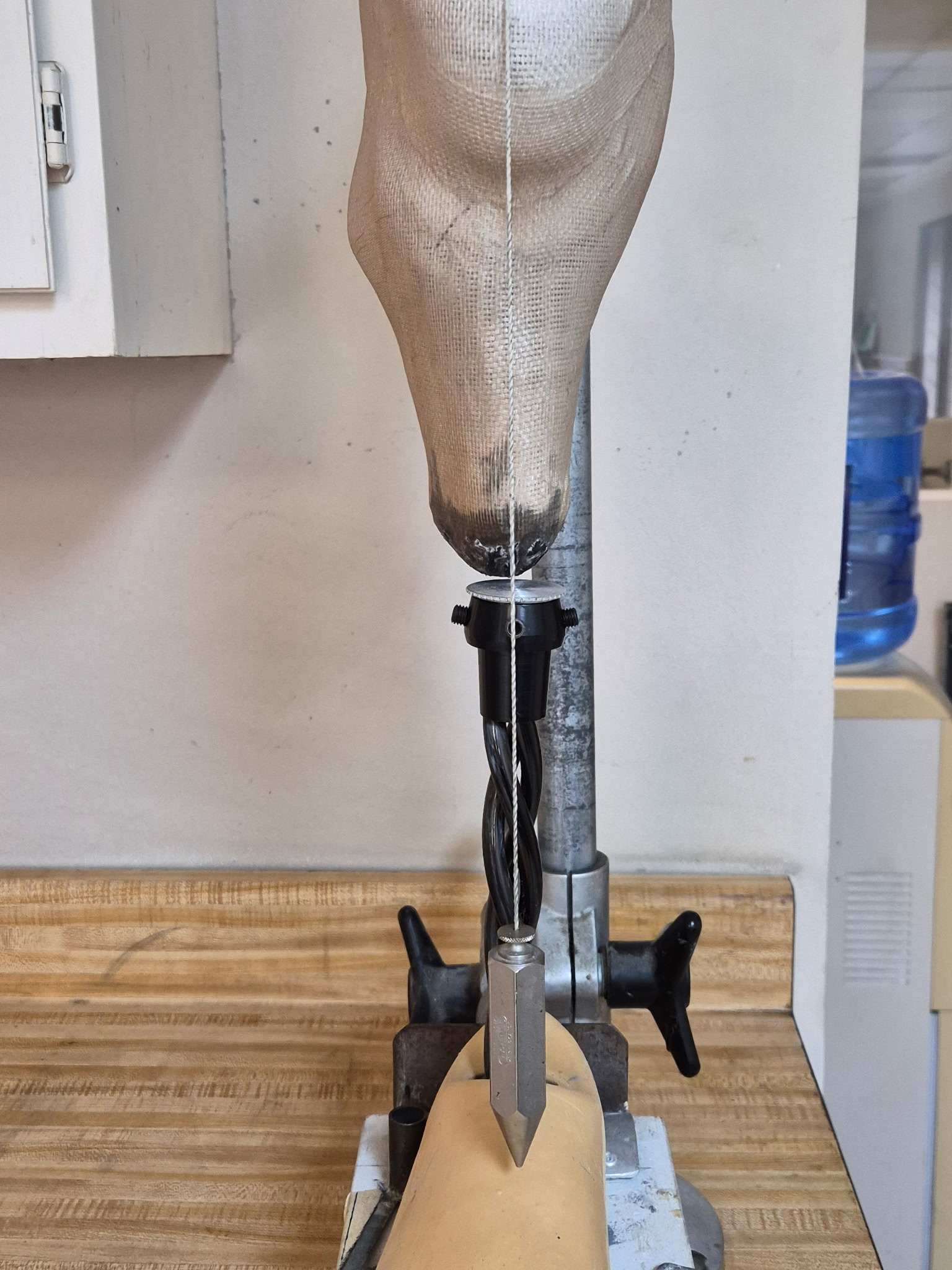 Figure 6 Figure 6 |
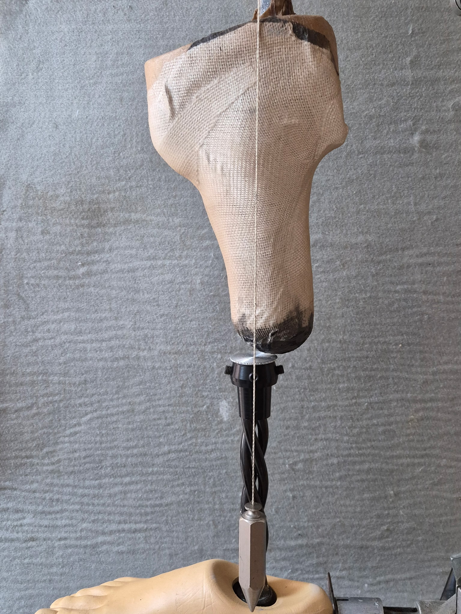 Figure 7 Figure 7 |
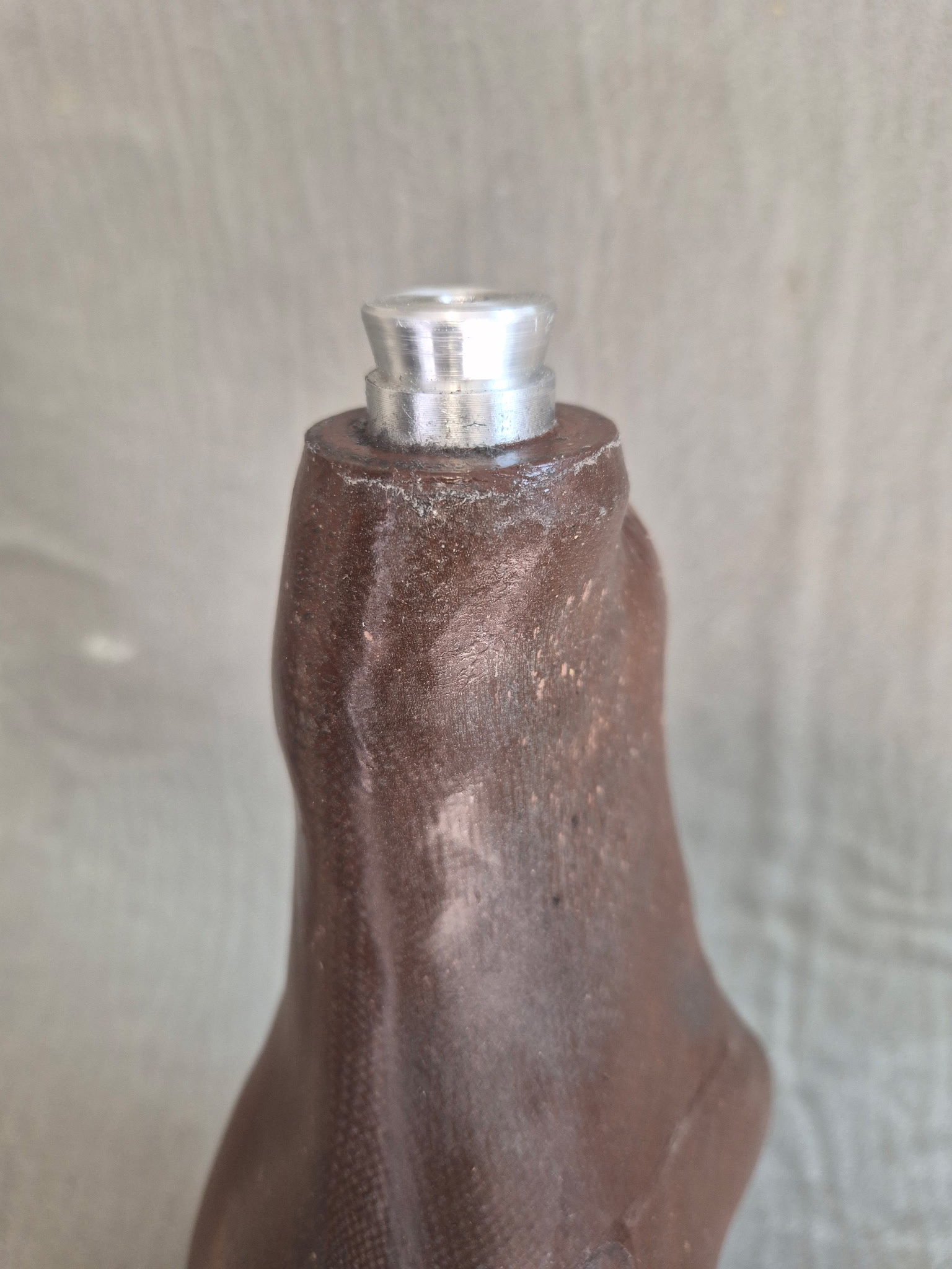 Figure 11 Figure 11 |
 Figure 12 Figure 12 |
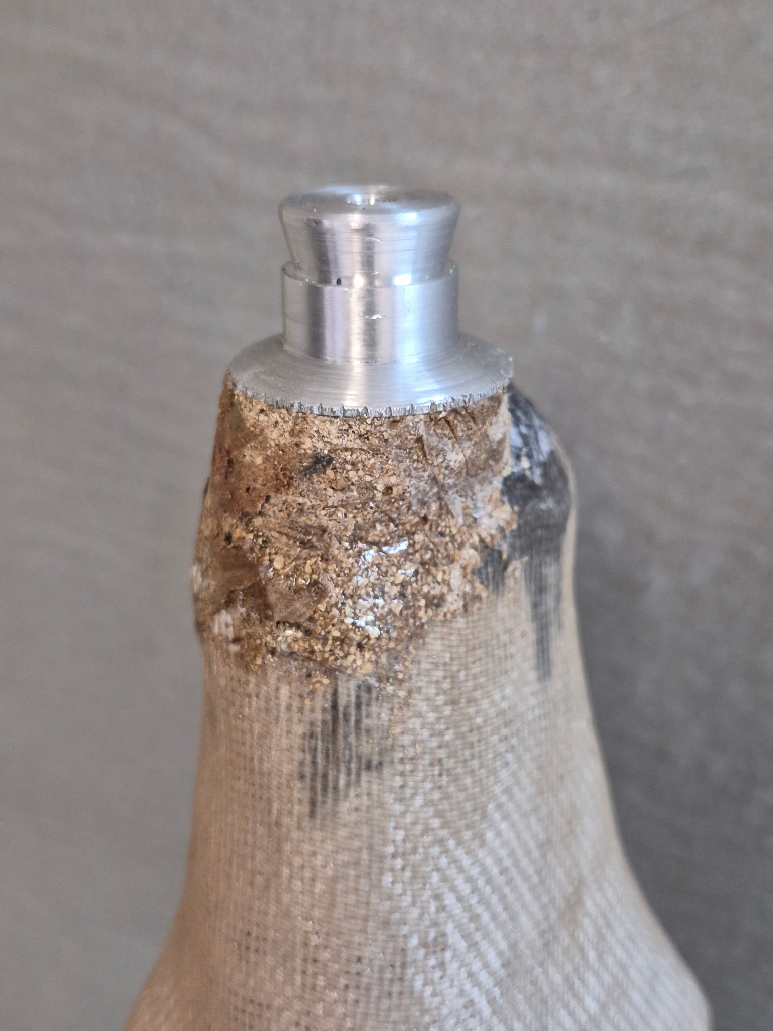 Figure 8 Figure 8 |
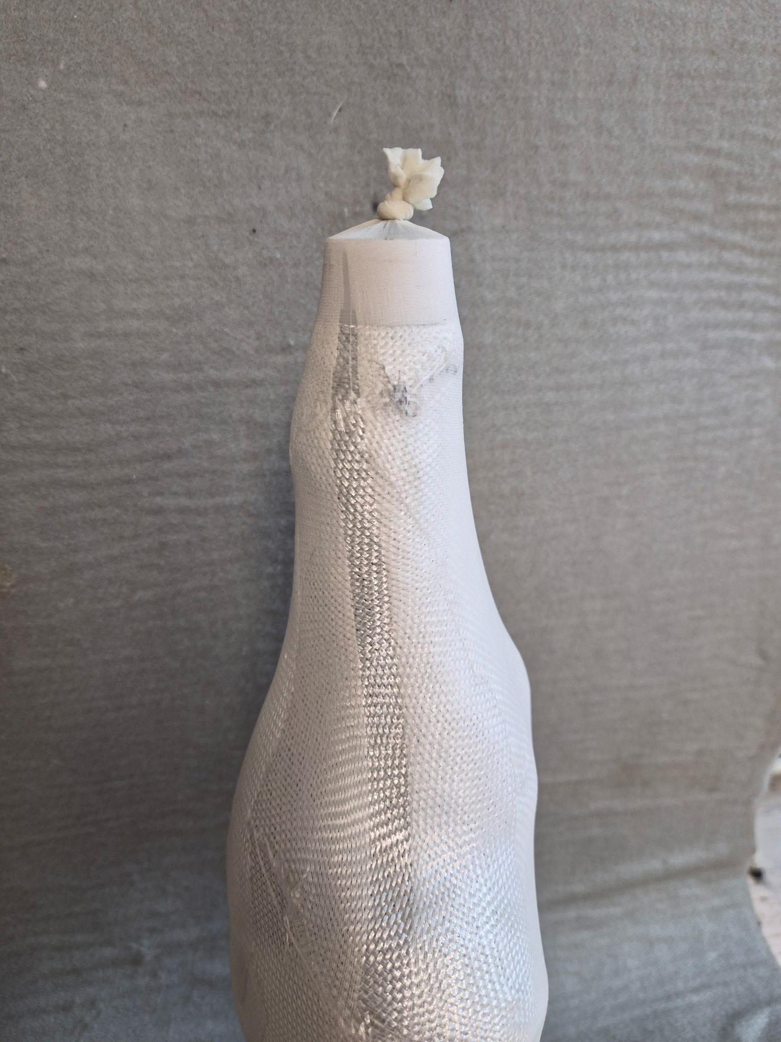 Figure 9 Figure 9 |
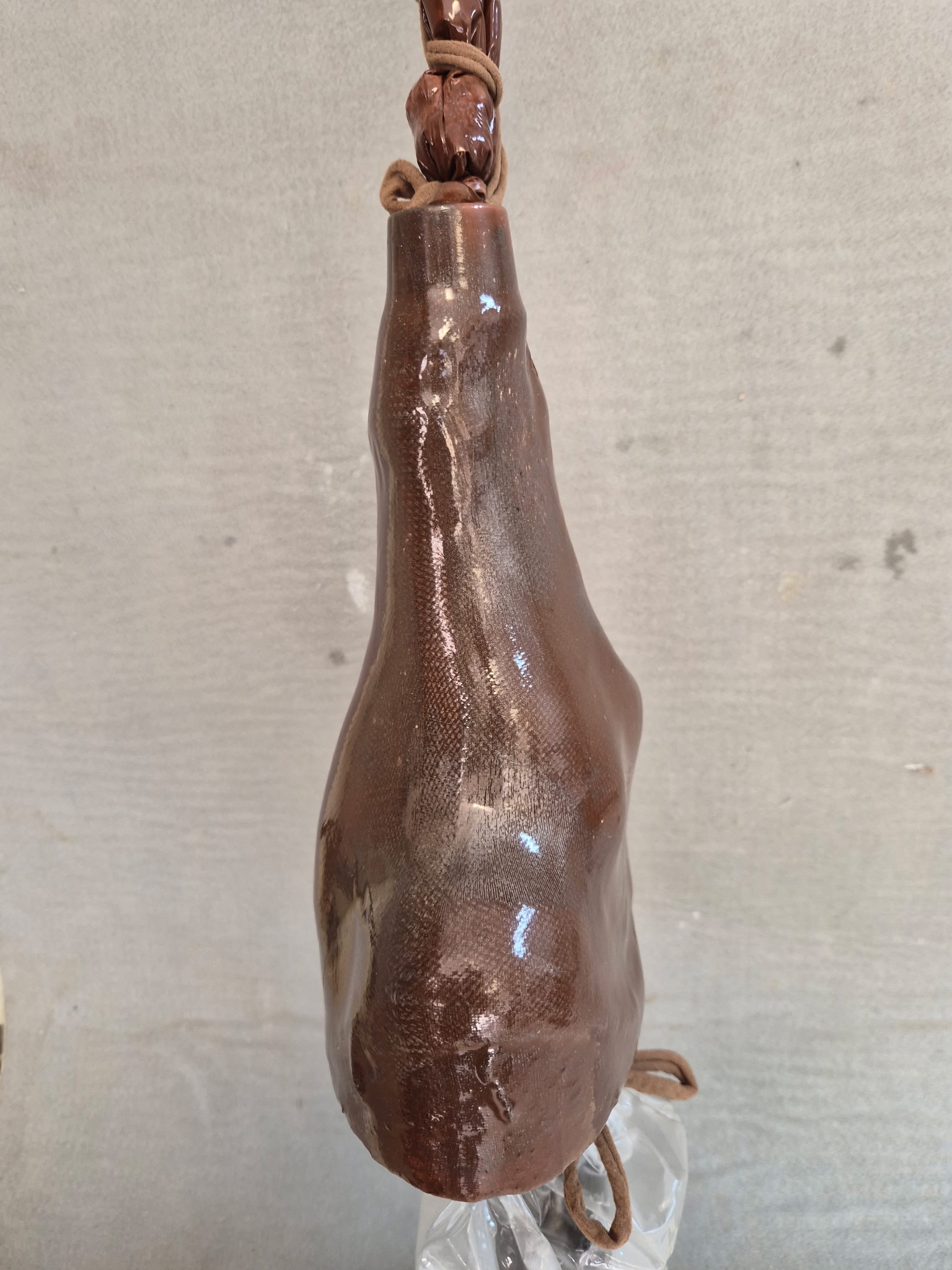 Figure 10 Figure 10 |
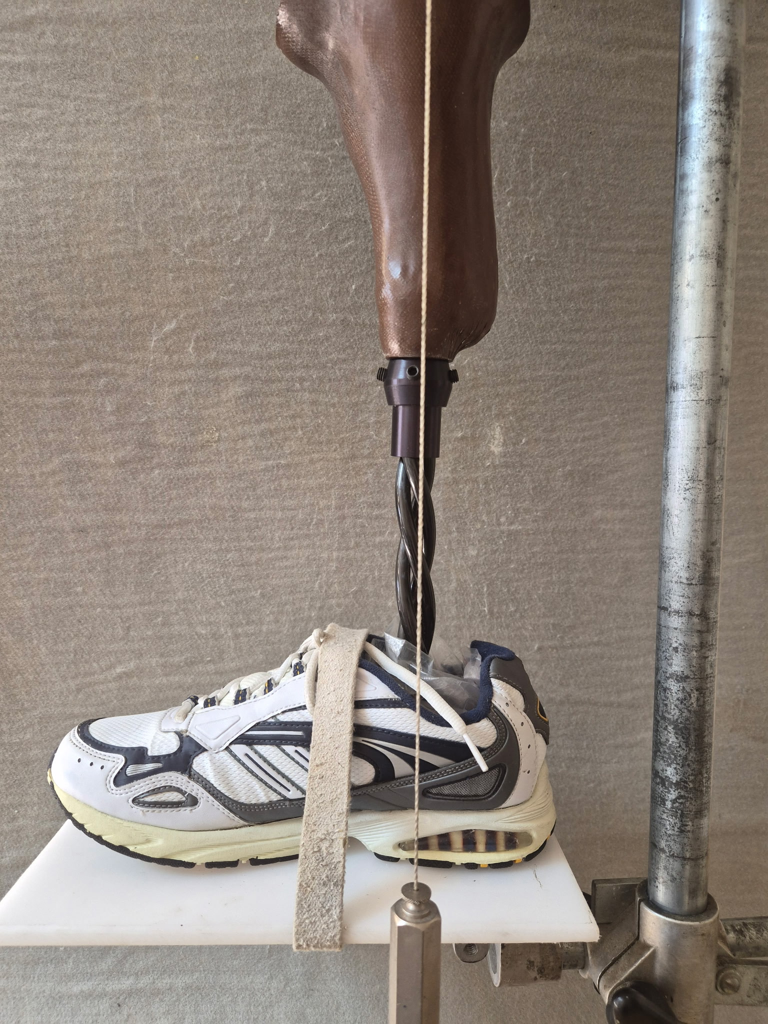 Figure 13 Figure 13 |
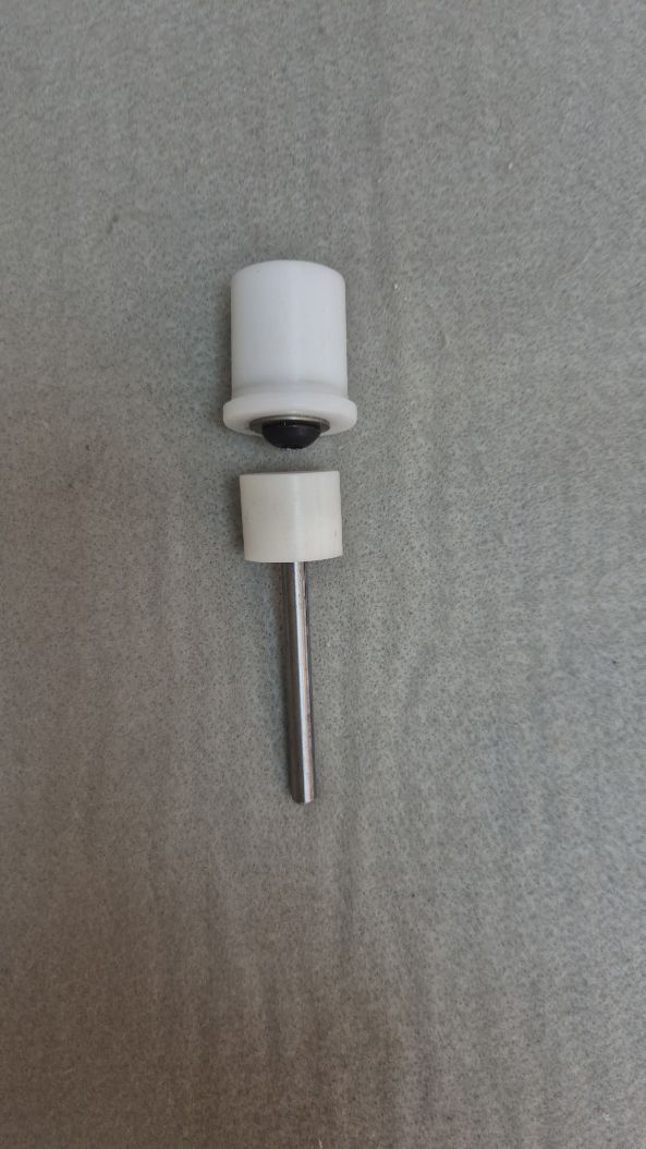 Figure 15 Figure 15 |
Dycor Manufacturing, Inc. 2711 Cartwright Road Missouri City, TX 77459 ph: 832.781.8343![]()
© 1997 - , Dycor Manufacturing Inc., All rights reserved.